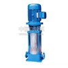
The structural characteristics and working principle of the multi-stage pump are thoroughly analyzed. Today, Zhongheng self-priming pump is here to share some essential knowledge about multi-stage pumps with you.
Multi-stage pumps are designed in a segmented form, consisting of multiple single-stage units connected in series. Each stage increases the pressure of the fluid, allowing the pump to achieve higher lift and pressure than a single-stage pump. The water intake section is positioned vertically, and the discharge nozzle directs the liquid upward. Depending on the number of stages required, the pump can be assembled accordingly. The precision of each component’s alignment significantly affects the pump's performance, especially the impeller outlet and the guide vanes on both sides. Even minor misalignments can cause flow disruption and reduce efficiency. This is particularly important after maintenance, as improper assembly can lead to serious issues in the entire system.
Currently, the main components of a multi-stage pump include the inlet section, outlet section, impellers, guide vanes, shaft, sealing rings, balance disc, bushings, tail cover, and bearing housing. The impeller is made from high-quality cast iron and features internal blades. The liquid enters axially from one side, and due to the different pressures on either end, an axial force is generated. This force is counteracted by the balance disc, which is tested for static balance during manufacturing. The sealing ring, also made of cast iron, prevents high-pressure water from leaking back into the suction area and is installed in the inlet and middle sections. It is a wear part that can be replaced when damaged. The balance disc, made of wear-resistant cast iron, is located in the packing chamber and helps stabilize the impeller while protecting the pump shaft. It too is a replaceable component. The shaft, made of high-quality carbon steel, has the impeller fixed to it using keys, bushings, and nuts. One end connects directly to the motor via a coupling. We won’t go into more details here. Next, let’s explore how a multi-stage pump works.
A multi-stage pump is a type of centrifugal pump that uses the rotation of the impeller to generate centrifugal force, which then moves the fluid. When the gas density reaches the operational range of a mechanical vacuum pump, it is extracted, gradually achieving a high vacuum.
The pump body is filled with an appropriate amount of water, acting as a working fluid. As the impeller rotates clockwise, the water is thrown outward by centrifugal force, forming a uniform ring inside the pump casing. The lower inner surface of the water ring just touches the impeller hub, while the upper inner surface makes contact with the blade tips (with a certain depth of insertion). This creates a crescent-shaped space between the impeller and the water ring, divided into several small cavities by the blades.
If the lower part of the impeller is at 0°, the volume of these small cavities decreases as the impeller rotates from 180°, allowing them to communicate with the suction port. At this point, gas is drawn in. Once the suction is complete, the cavity becomes isolated from the suction port. As the impeller continues to rotate, the cavity expands and contracts, compressing the gas. Finally, when the cavity aligns with the exhaust port, the compressed gas is expelled from the pump.
In summary, a multi-stage pump achieves suction, compression, and exhaust through changes in the pump chamber volume, making it a type of centrifugal pump that operates by volume variation.
For more information on valves and pump systems: Pneumatic Valve, Pneumatic Adjustment Valve, Stainless Steel Butterfly Valve, Hard Seal Ball Valve, Pair Ball Valve.

IECEx Approved Coriolis Mass Flow Meter
Zhejiang Sealand Technology Co., Ltd. is a trustworthy manufacturer of Mass Flow Transmitter, Coriolis Mass Flow Transmitter, Coriolis Mass Flow Sensor, Mass Flow Sensor & Mass Flow Sensor Coriolis, ATEX, IECEx & CE approved.
The meter can be connected with computer as follows. Connect the meter and computer with a USB-to-RS485 converter( converter A+ end to transmitter A+ end, B- to B-, and GND to GDN); turn to device manager of the computer to check COM port connected with meter. Start the software, select the right COM port and click Connect; do not change any other parameters (if you do not know the right one, click Automatic options on the left, click Connect, plug & unplug the transmitter, and then check if it is connected). You can click Connect on the tool bar to disconnect or connect again. It will shown Connected/Not Connected at the bottom of this interface.
The flow direction is settable. There are 4 options, forward(default), reverse, absolute value & bi-direction. There is a direction mark on the sensor. Forward means the same direction with the mark on sensor, the meter will only count the flow in this direction; reverse means the opposite direction of the mark, the meter will only count the reverse direction; bidirectional means that the meter will measure both directions, it increases when it is forward and decreases when reverse; absolute means it increases no matter it is forward or reverse.
Mass Flow Transmitter, Coriolis Mass Flow Transmitter, Coriolis Mass Flow Sensor, Mass Flow Sensor, Mass Flow Sensor Coriolis
Zhejiang Sealand Technology Co., Ltd. , https://www.sealandflowmeter.com