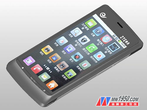
ZTE's Blade series has made a remarkable sales success both domestically and internationally. It's a mobile phone I really admire. With the 3D efficient CAD/CAM function of Zhongwang 3D, it's possible to create a realistic 3D CAD model of the ZTE N880. Additionally, this 3D CAD tutorial is quite straightforward, enabling you to quickly design an attractive 3D mobile phone model.
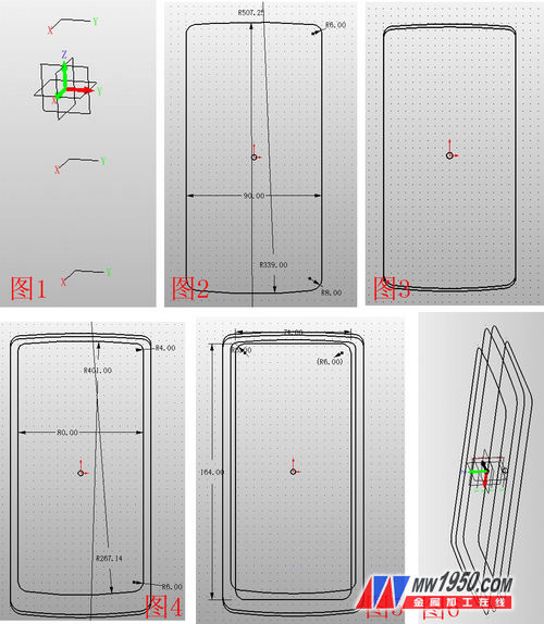
1. First, create three XY datums offset by -5, -13, and 5, and name them as Datum 1, 2, and 3. Insert sketches in the XY plane corresponding to each datum. The resulting sketches—Sketch 1, 2, 3, and 4—are shown in Figures 2, 3, 4, and 5 (note that Figure 3 overlaps with Figure 2 but is shifted down by 2 cm). The final result is illustrated in Figure 6.
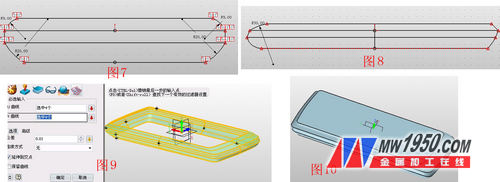
2. Next, insert Sketches 5 and 6 on the XZ and YZ planes respectively. Connect reference points as shown in Figures 7 and 8. Then, set the four curves from both sketches into a curve list named Curves 1, 2, 3, and 4. Click on U/V surface, select the U curves as Sketch 4, 1, 2, 3, and V curves as Curve 1, 3, 2, 4. The result is displayed in Figure 9. Then, use the N-edge surface feature to repair the upper and lower sides, as shown in Figure 10.
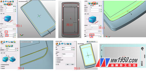
3. Perform a stretch-subtraction operation using the surface shown in Figure 11. Note that the offset term should be "thickening," with offsets 1 and 2 set to 0 and 0.2 respectively. This step creates the gap between the phone screen and the shell. Then, insert Sketch 7 on this side, draw a rectangle, and add an arc below it, as shown in Figure 12. Use the stretch-subtract operation again, selecting the arc as the contour, and choose "shrink/expand" for the offset with a value of 0.1. The chamfered edge is shown in Figure 13. Then, use the surface-curve segmentation tool, selecting the highlighted face and curve as shown in Figure 15. This helps split the faces for easier coloring. Insert Sketch 8 on Reference Surface 4, draw the icon shown in Figure 16. Remember to use the "explode" function to make the text editable before proceeding with surface segmentation.
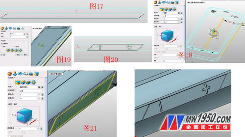
4. Insert Sketch 9 on the YX surface and draw the shape shown in Figure 17. Stretch Sketch 9 with the parameters in Figure 18. Then mirror the stretched shape using the YZ surface, as shown in Figure 19. Insert Sketch 10 on the YZ plane, draw the shape in Figure 20, and then add or subtract the diamond border along with the "+" and "-" symbols. The final effect is displayed in Figures 21 and 22.
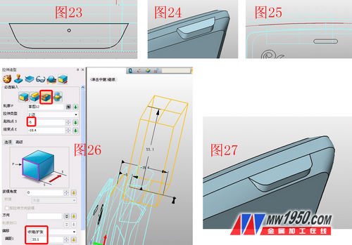
5. Insert Sketch 11 on the XZ plane and draw the figure in Figure 23. Use the stretch-plus operation on Sketch 11, as shown in Figure 24. In the XY plane, sketch 12 involves drawing a circular arc along a reference curve, as shown in Figure 25. Apply the stretch-minus operation on Sketch 12 with the parameters in Figure 26. The result is shown in Figure 27.
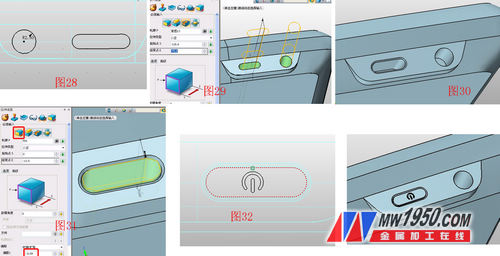
6. On the XZ face, insert Sketch 13 and draw the shape in Figure 28. Perform a point stretch-minus operation, stretching Sketch 13 and rounding the groove edges, as shown in Figures 29 and 30. Then, click on the stretch-base operation, selecting the bottom face of the groove, as shown in Figure 31. Insert Sketch 14 on the XZ plane, draw the shape in Figure 32, and apply the stretch-decrement operation, as shown in Figure 33.
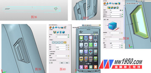
7. Insert Sketch 15 on the XY plane and draw the shape in Figure 34. Stretch the knife frame and use the surface segmentation function to divide the blade surface with a circle from the sketch for easier coloring. The parameters are shown in Figure 35. Pay attention to the projection direction. The rounded corners of the blade and surface are angled, as shown in Figure 36, with inverted angles and specific parameters.
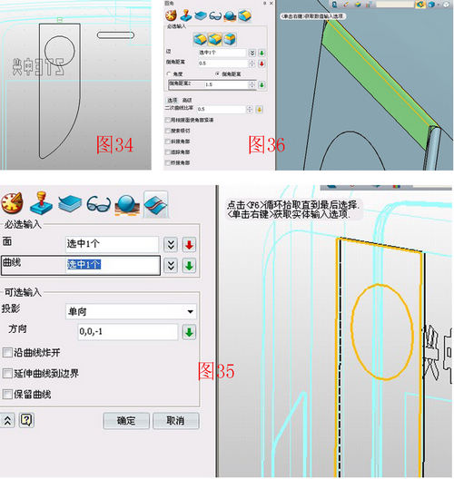
8. Insert Sketch 16 on the YZ plane and draw the shape in Figure 36. Use the stretch-minus operation to stretch Sketch 16 on both sides, creating the speaker hole and USB port, as shown in Figure 37. Then, use the stretch-base operation, selecting the bottom surface of the USB hole, as shown in Figure 38. Finally, use the shape-hexahedron feature to draw a box in the appropriate area, as shown in Figure 39. To enhance realism, download the N880 menu screen from the internet and apply it as a texture map in the correct position, as shown in Figure 40.
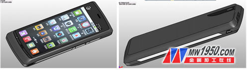
Finally, using the visual style-surface properties, the beautiful N880 3D CAD model is completed with various colors. The final image is shown below. If you're interested, try creating your own 3D CAD model of a mobile phone! Download the 3D model for free now and get the latest 3D CAD/CAM tutorials. You can also download the 3D CAD drawings of this tutorial from the 3D Exchange Zone of the Zhongwang Technology Community. As a "3D CAD learning material," you can build your own resource library.
Blinds Glass,Fabric Vertical Blinds,Vertical Blinds Fabric,Blind Shutter Glass
Huaian Hongrui Glass Co.,Ltd , https://www.hongruiglass.com