Straight bevel gears are mainly used for the transmission of two axes. The angle between the two axes is usually 90° or less than 90°. Bevel gears are generally machined on special machine tools such as bevel gears. In the absence of bevel gear special machine tools, bevel gear milling cutters can be used on milling machines, which use forming tools and indexing devices for machining on milling machines. Due to the indexing error and tool mounting error, only 9 to 10 precision gears can be machined. In addition, the machining process requires multiple discontinuous teething and low productivity. It is only used for gears with low machining accuracy in single-piece small batch production and repair work.
Straight bevel gear example
The parameters of the straight bevel gear are shown in Table 1. The structure and technical requirements are shown in Figure 1.
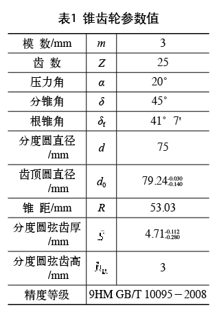
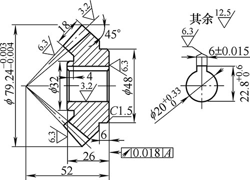
Figure 1 Straight bevel gear
2. Processing method and steps of straight bevel gear
(1) Select the bevel gear milling cutter. Since the diameters of the big end and the small end of the bevel gear are not equal, the diameters of the base circle of the large and small ends are not equal, the involute tooth shape of the big end is relatively straight, and the small end is relatively curved. The bevel gear tooth shape milled by the forming cutter cannot conform to the small end if it is to conform to the big end. Therefore, in the milling machine, the bevel gear is machined by the bevel gear milling cutter, and the tooth shape of the entire tooth is impossible to be all accurate, so the precision is low.
The bevel gear is designed with the parameters of the big end as the standard. For this reason, the tooth profile of the bevel gear milling cutter should be manufactured according to the big end. In addition, since the small groove of the bevel gear has a narrow groove, the groove width of the small end of the standard bevel gear is 2/3 of the large end, so the thickness of the bevel gear milling cutter should be made according to the small end, and should be slightly thinner than the small end groove. . Bevel gear milling cutters are different from ordinary cylindrical gear milling cutters in that they are marked with a "" mark on the side of the bevel gear milling cutter to prevent mis-selection.
Since the teeth of the bevel gear are on the conical surface, the tooth profile of the bevel gear milling cutter should be the same as the tooth profile on the cross section perpendicular to the indexing conical surface. The bevel gear milling cutter is also like a cylindrical gear milling cutter. Each modulus is divided into 8 tool numbers according to the degree of bending of the tooth profile curve, as shown in Table 2. The difference is to choose by the number of equivalent teeth. In this example, the No. 4 milling cutter is not selected according to 25 teeth, but the equivalent number of teeth should be calculated first.
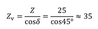
That is, a bevel gear milling cutter with a modulus of 3 mm should be selected for 35 teeth.
(2) Fixing and adjustment of the workpiece. Before the workpiece is clamped, the blank should be inspected, and the corner angle and the back cone angle should be checked with a 10,000-angle angler; the distance from the reference surface to the outer circle should be checked; and the outer diameter of the blank should be checked.
The clamping of the workpiece. According to different structural shapes, the commonly used clamping method for bevel gears is to clamp with a mandrel and a nut. The Morse cone of the mandrel handle is matched with the taper hole of the indexing head spindle, and is fastened to the indexing head by a tensioning screw. The workpiece is placed on the cylindrical part of the mandrel, and is corrected by a dial gauge and then pressed with a nut (see Figure 2).
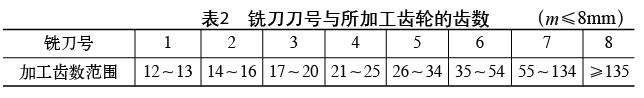
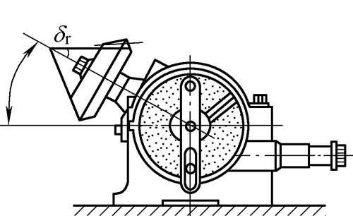
figure 2
For bevel gears with small diameters and large taper angles or small end groove bottoms close to the inner bore surface (see Figure 3), to avoid damage to the nut or even the mandrel during milling, a taper of 1:8 000 can be used. The 1:1 micro-cone spindle clamping should be determined according to factors such as the tolerance class of the aperture.
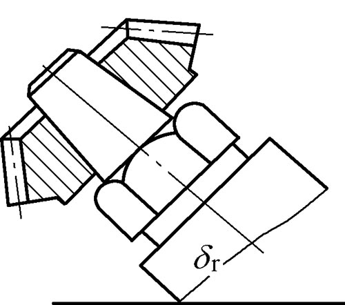
image 3
For workpieces with a large taper angle and a large diameter, a stepped end or a large aperture, etc., the three-jaw self-centering chuck can be directly used for clamping on the indexing head.
Correction of the workpiece during clamping. If the bevel gear is clamped with a dedicated spindle or spring chuck, it is generally not necessary to perform alignment. If the micro-cone spindle is used for clamping, it is generally not necessary to find the right end. If necessary, the end face of the large end of the bevel gear can be inspected and corrected. When clamping with a chuck and clearance mating mandrel, it is necessary to find the radial round jump of the big end and the small end of the workpiece, and the end face round jump of the big end.
Adjustment of the indexing head. When the indexing head is mounted on the worktable, the spindle axis must be aligned with the feed direction, and then the indexing head spindle is pulled up by a cutting angle whose size is equal to the root taper angle δf.
Adjustment of the depth of the milling layer. After the workpiece and the indexing head are adjusted, adjust the mid-section of the milling cutter to the axis of the workpiece (the tool is centered), and then wipe the cutter to the large-end tapered surface (based on the big end). And exit the workpiece, raise the table to a full height (2.2m), you can start milling the middle of the slot. A workpiece with a large modulus can be divided into several passes in depth.
In order to prevent the accident caused by the sudden start of the indexing head spindle during cutting, the direction of the cutting is preferably from the big end to the small end.
(3) Principle and method of partial milling. Both the teeth and the slots of the bevel gear are of a contracted type, that is, wide at the large end and narrow at the small end. Although the indexing head has been erected with a root taper angle δf during machining, the large end of the outer conical surface of the bevel gear is slightly higher than the small end, and the big end is cut deeper than the small end during milling, and the large end of the cogging width is also It is slightly wider than the small end, but this difference can not meet the requirements. It is also necessary to mill more sides on the big end slots. When milling the bevel gear on the milling machine, after the first feed is milled out of the intermediate cogging, the tooth shape of the big end is obtained, but the groove width size is not up to the requirement, so each tooth groove is generally milled three times to reach The purpose of milling the sides of the large end slots is to cut the balance on both sides of the bevel gears. The principle of partial milling is to deflect the workpiece on the one hand and to move the table on the other hand to realign the small end slots with the milling cutter. When the workpiece is deflected, the difference between the big end and the small end in the direction perpendicular to the feed direction (lateral direction) makes the milling allowance gradually increase from the small end to the big end, and the big end is milled more.
At present, there are many methods of partial milling when milling bevel gears, but due to the inconsistency of the ratio of the pitch to the tooth width (ie R/b), and the parameters such as the pitch angle and the number of teeth, neither method can be applied to all cones. Gear processing, therefore, can only be selected according to the specific circumstances, and corrected in the trial cut. Milling is often performed using a combination of the amount of rotation and the offset, as shown in Figure 4.
the first method. The offset S is first calculated, and the amount of rotation of the workpiece about its own axis is determined by trial cutting. There are several calculation methods for S values, and one of them is introduced.

Where T is the thickness (mm) of the milling cutter at the middle diameter; x is the offset coefficient (see Table 3).
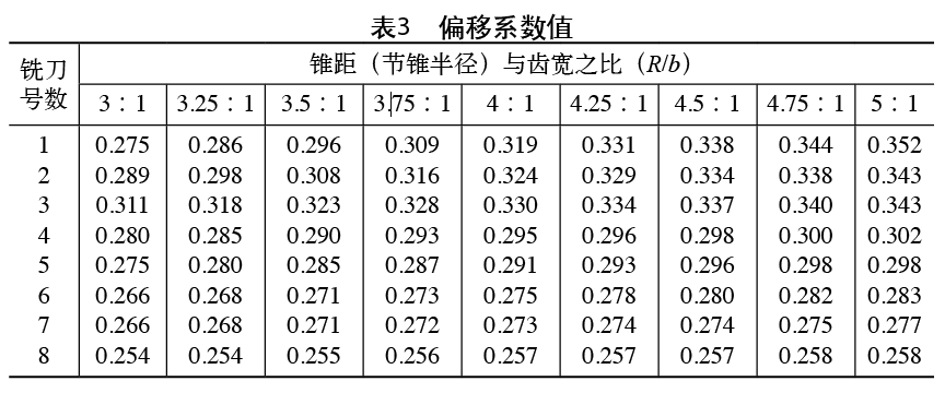
Taking the bevel gear shown in Fig. 4 as an example, if a gear caliper is used to measure T=2.58 mm from the milling cutter, and x=0.266 is found from Table 3, then S=T/2-mx=2.58÷2-3× 0.266 = 0.492 (mm).
That is, when machining, when the intermediate cogging is milled, the table is laterally offset by S=0.492 mm, and then the indexing handle is shaken to realign the small end tooth groove with the milling cutter, and the amount of rotation of the handle N is recorded. One side of the slot. When milling the other side of the tooth groove, the table should be moved backward by 2S = 0.984 mm and the reverse rotation of the handle is 2N.
The second method. First, the amount of rotation N of the indexing head handle is counted, and the offset S of the table is determined by trial cutting. There are several ways to calculate the value of N. I will introduce one of them.
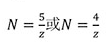
In the formula, z is the number of teeth of the bevel gear, and when the number of teeth is small, 4/z is taken; when the number of teeth is large, 5/z is taken.
Still taking the bevel gear of Figure 4 as an example,
That is, in the case of partial milling, first turn the handle over 4 holes in a circle of 25 holes, and then move the table laterally to realign the small end slots with the milling cutter and note the offset S value.
The third method. Milling is performed by combining the deflection angle of the indexing head in the horizontal plane with the offset. First, the deflection angle α of the indexing head and the workpiece in the horizontal plane is calculated, and the offset S of the lateral direction of the table is determined by trial cutting. Can be calculated by the following approximate formula

Where R is the bevel gear taper (mm).
Taking the bevel gear of Fig. 4 as an example, the deflection angle α is
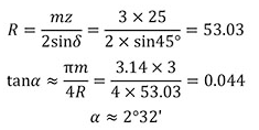
In the case of partial milling, use the turntable mounted under the indexing head to rotate the indexing head through 2°32', and then move the table laterally to realign the small end tooth groove with the milling cutter and record the offset S. value.
(4) Correction method of tooth thickness during partial milling. After the two sides of the two to three teeth are subjected to the eccentric milling by the above method, the large and small ends of the teeth should be detected. The formula for the small chord tooth thickness and the chord height is as follows
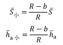
Generally, if there is a sum on the pattern, the sum can be obtained by the value or ratio of R and b. In this case, =4.71mm, =3.0mm, =3.11mm,
=1.98mm. If the actual measured value does not match the value indicated or calculated on the drawing, the amount of rotation and offset should be corrected. The principle of correction is:
If the small end size is accurate and there is a margin at the big end, the amount of rotation N (or the deflection angle α) and the offset S should be increased to increase the difference so that the small end is no longer milled.
If the big end size is accurate and the small end tooth thickness has a margin, the amount of rotation N (or the deflection angle α) should be reduced to reduce the offset S much more. The small end is also milled out, and the big end is no longer milled.
If there are margins in both the big end and the small end, and the margin is equal, then only the offset S is reduced, so that both the big end and the small end are milled.
If the small end size is accurate and the big end size is too small, the amount of rotation N (or the deflection angle α) should be reduced. The offset S is appropriately reduced so that the small end is no longer milled, and the big end is less cut than the original. Go some.
If the big end size is accurate and the small end size is too small, the amount of rotation N (or the deflection angle α) should be increased, and the offset S is increased a little more, so that the small end is milled less than the original. If the tooth thickness of the small end is too small when milling the intermediate groove, it is necessary to change the milling cutter or manufacture a special milling cutter for machining.
3. Conclusion
The milling bevel gear on the milling machine is an approximate machining method. The smaller the number of teeth of the gear, the larger the error. The milled small end tooth groove curve is flatter than the required one, and the tooth top thickness is large. In the actual work, if the tooth thickness of the big end and the small end of the bevel gear are processed more accurately, and the transmission meshing gap of the pair of bevel gears is smaller, the tooth surface curve of the small end is too straight, and the small end of the movement is small. There will be interference. Therefore, after the bevel gear is milled, the tooth surface of the bevel gear is repaired by using a fine boring tool, so that the small end curve is slightly bent, close to the correct tooth shape, and the repair amount is gradually reduced from the small end to the big end. When the requirements are not high, the small end tooth thickness can be made slightly smaller in order not to repair and avoid interference.
references:
[1] Wang Zhenqiang. Processing of Straight Bevel Gears by Ordinary Milling Machine[J]. Modern Manufacturing Technology and Equipment,2004(3):29-30.
The air, which is drawn in by the motor of a Heat gun, is electrically heated. The desired temperature can be set to between 100 to 600 and can be maintained electronically, independent of the required are flow rate. Various possible applications include thawing, drying, tinning, sharping, setting and removal of old coats of paint and staring adhesive processes.
Hot Gun,Electric Hot Air Gun,Hot Air Gun,Heat gun
AWLOP CO.,LTD , https://www.awlop.com