The pipeline pump is a general-purpose pump product with a large quantity and wide range. However, due to various varieties and specifications, each type of product cannot be mass-produced. Therefore, each pump manufacturer adopts a production mode of small batch rotation. Although the extensive application of economical CNC machine tools has changed the production mode of one person, one machine and one knife, it has not fundamentally changed the backward production mode of the pump industry. The pipeline pump is the largest production of our company, accounting for about one-eighth of the entire domestic market. In order to improve the processing efficiency of the pump body of the pipeline pump, a numerical control special combined machine tool was jointly developed by the factory and the school to complete the processing of the inlet and outlet flanges and the middle hole of the pump body of the pipeline pump.
1. The structure of the special machine tool
The special machine tool consists of three CNC milling heads. In order to meet the design requirements of the pump inlet and outlet and the middle channel, the rotary centers of the three milling heads are arranged in the same plane, two in the horizontal direction and one in the vertical direction. The milling head can be moved along its own guide rails to achieve machining of different sizes of the pump body. A tool is placed on each milling head and the feed of the milling head and tool is controlled by the program. The structure of the special plane is shown in Figure 1.

figure 1
1. Horizontal guide rail 2. Longitudinal guide rail 3. Backing plate 4. Base 5. Milling head 6. Hydraulic clamping device 7. Workpiece positioning seat
The pump body is mounted on a special fixture that is mounted on a CNC slide that can be moved back and forth. The slide is moved to the outside to facilitate the mounting of the workpiece and then moved inward to the machining position. After the workpiece reaches the machining position, there is a hydraulic cylinder on the side of the guide rail to eliminate the backlash of the sliding dovetail groove and prevent the vibration of the clamp and the pump body during processing. After the workpiece is finished, the top hydraulic cylinder is retracted, and the slide table moves to the outside together with the workpiece to load and unload the workpiece. The pressing of the workpiece is completed by a hydraulic cylinder, the pressing speed is fast, and the workpiece is fixed reliably.
2. Adjustment of pump processing technology
According to the design requirements, the vertical milling head of the special machine should complete the machining of the middle end d1 end face, d2 hole and bottom surface, d3 hole and bottom surface and end face. The milling heads on both sides complete the processing of the outer circle and the end face of the inlet and outlet flange d4 and the end face of d5. The pump body parts are shown in Figure 2.
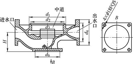
figure 2
In order to adapt to the processing requirements of the special machine, the original pump processing technology was adjusted. The original process is to first process the other parts of the pump body, then process the bottom surface of the pump body and finally drill. In order to adapt to the processing of the special machine, the bottom surface of the pump body is processed in the front, that is, the foot surface is first machined, four mounting holes are drilled, and the process hole d6 is processed on the bottom surface of the pump body.
The pump body pattern only requires machining of the bottom surface of the pump body to ensure that the center height H is sufficient, and no processing requirements are required for the d6 hole (formerly casting). In order to provide a precise positioning reference for machining on a special plane, the d6 cast hole is changed to the machining hole of the precision H8, so that one side and one pin are positioned, and the degree of freedom of rotation in the horizontal plane is not limited. The reason is: 1 foot surface The design accuracy of the four holes on the top is not high. To meet the accuracy requirements of the positioning holes, it is necessary to increase the processing cost. 2 With one of the four holes, it is necessary to ensure the mutual position (shape tolerance) of the pump and the inlet and outlet flanges. It is difficult to meet this requirement due to casting errors. Therefore, the degree of freedom required to be positioned is placed in the workpiece installation and solved by the design of the pallet.
In order to ensure the size H of the pump body after processing, it is necessary to ensure the height dimension of the tooling and the H' size when the pump body is pre-machined. Because the center height of the milling head on both sides of the special plane is fixed, the height of the tooling plus the center height H' of the pump body is equal to the center height of the milling head on both sides of the plane, so that the size H after machining can be guaranteed. The height dimension of the tooling is easy to control, and the center height H' of the pump body should be taken care of. In order to ensure the size H', the original bottom surface is machined with a three-jaw self-centering chuck to support the d7 hole, and the d1 end surface (see Fig. 3), to the three-jaw self-centering chuck to support the d7 hole and the flow channel base round surface. (longer jaws). Because there are defects in the d1 end face that cannot be avoided by casting processes such as blanks and risers, such as grinding in the blank cleaning, it will affect the consistency of the size H' of the center line of the pump inlet and outlet to the bottom surface of the pump body and its parallel. degree. The flow path base round surface is the most demanding over-flow part in the pump body casting, with few casting defects, good surface roughness quality and high precision. With it as the processing reference, the size H' can be reliably guaranteed.
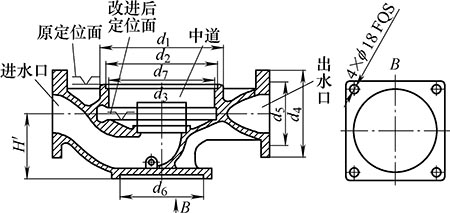
image 3
3. Tooling design
The tooling is mainly composed of a base, a transition plate, a bottom plate, a guide pin, a traveling plate and a positioning plate, as shown in FIG. 4 .
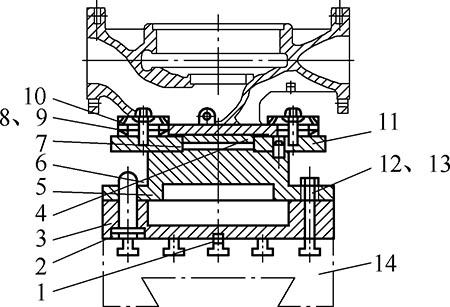
Figure 4
1. Positioning key 2. Hexagon socket head cap screw M10 3. Base 4. Positioning plate 5. Base plate 6. Guide pin 7. Locating pin 8. Stud bolt 9, 13. Nut 10. Press plate 11. Accompanying plate 12. T-bolt 14. Slide table
The base and the worktable are positioned and coupled by the positioning key. Because the center height of the pump body is different, the spacer is sometimes added between the base and the bottom plate. In order to ensure the mutual positional relationship between the two, the two guide pins are used for positioning and coupling. The accompanying plate and the bottom plate are positioned by one side and two pins; the positioning plate is designed to adapt to different pump body positioning holes d6 and reduce the number of the accompanying plates. For processing different pump bodies, only the positioning plate needs to be replaced. The pump body and the traveling board are positioned by one side and one pin, and the degree of freedom of horizontal rotation depends on the position of the pump body on the installation platform on the outside of the machine tool. After the pump body and the accompanying plate are positioned, the pump body and the accompanying plate are fixed by the pressure plate, and are hoisted to the machine tool, and then the workpiece is fixed with the hydraulic clamp to process the workpiece, and the hydraulic jaw is mounted on the bottom plate.
The shape and position error of the pump body casting blank is difficult to avoid. In order to adapt to the shape and position error of the pump casting blank, a method of correcting the installation of the pump body outside the machine tool was adopted, and a mounting platform was deliberately designed. On the installation platform, the operator can reasonably distribute the error of the pump body casting blank to ensure the same flange machining allowance at both ends of the pump body, and then fix the pump body and the pallet with the pressure plate to form a whole. The structure of the installation platform is shown in Figure 5.
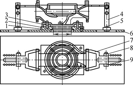
Figure 5
1. Accompanying board 2. Accompanying board positioning plate 3. Pump body positioning plate 4. Bracket 5. Bolt 6. Mounting plate 7. Finding block 8. Nut M16 9. Pin shaft
The installation platform is mainly composed of a mounting plate, a aligning block, a lining plate and a bracket. There is a pallet positioning plate on the mounting plate, and the accompanying plate and the mounting plate are formed by the two-pin positioning of the accompanying plate positioning disk and a diamond pin. A guiding groove is formed on each side of the mounting plate for adjusting the proper mounting position according to the size of the pump body, and the center of the guiding groove is in line with the center of the positioning plate of the accompanying plate. The aligning block can be rotated around the pin on the bracket and flipped away from the workpiece when not in use. When the pump body is hoisted to the mounting platform, the positioning hole d6 is installed with the aligning plate of the accompanying plate, and the pump body is rotated so that the direction of the inlet and outlet is aligned to the whole block direction, and the aligning block is turned over so that it falls on the inlet and outlet flanges. . If the positive block is in contact with the flange at the same time, the pump body is installed in the correct position; if it is not in contact, the pump body should be turned until it contacts at the same time. When there is a shape error between the inlet and outlet flanges of the pump body, the positive blocks at both ends cannot be in contact with the outer circle of the flanges at both ends. At this time, adjustment is needed to make the two ends find the positive block and the outer circle of the flange. The gaps present are on the same side and are equal, and the blank can be determined to be acceptable depending on the size of the gap. After the position of the pump body is adjusted, the pump body and the traveling board are fixed by the pressure plate, so that they are integrally hoisted together on the machine tool, and the bottom plate of the accompanying plate and the clamp is positioned by two pins, and then the hydraulic pressure is mounted on the bottom plate. After the jaws are pressed, they can be processed.
4. Characteristics of tooling
(1) Since each part of the tooling has a strict positioning mechanism relative to the machine tool table, when the different pump bodies need to be replaced, no adjustment is needed, and the assembly can be used after use, which shortens the auxiliary time.
(2) After the pump body is installed on the installation platform, it can be processed by lifting it onto the machine tool, no need to adjust it, and the adjustment and installation of the next part can be completed during the machining process of the machine tool, and the machining time and workpiece can be adjusted. The installation time coincides, which greatly reduces the auxiliary time and improves the processing efficiency of the machine tool.
(3) On the installation platform, the relative position of the pump blank and the pallet can be adjusted, so that the shape and error of the pump blank can be reasonably distributed (borrowing), avoiding the error concentrated at one end and causing the workpiece to be scrapped, and the unqualified blank can be Before the processing, it was found that the trouble of not being able to find the original pump body after lifting the pump body to the machine tool was avoided.
5. Precautions for tooling manufacturing installation
(1) To ensure that the center line of the inlet and outlet flanges coincides with the center line of the milling head spindle on both sides of the machine when the pump body is installed, it is necessary to rely on the manufacturing precision of several related parts of the tooling in the vertical direction (ie, the height direction). It is relatively easy, but it is more difficult in the horizontal direction. Therefore, the diamond-shaped positioning pin holes on the accompanying plate and the bottom plate should be adjusted after the pump body is adjusted in place on the machine tool, which can reduce the manufacturing difficulty of the tooling.
(2) Since the tooling and the workpiece should be moved back and forth on the longitudinal machine tool guide rail, the center line of the inlet and outlet flanges coincides with the center line of the milling head spindle on both sides of the machine tool during machining, and the preparation of the machining program should be paid attention to ensure the stopping position of the pump body. correct.
(3) During the design of the special plane, the three rotary heads of the milling center are coplanar. The center of the vertical milling head is on the center line of the longitudinal rail. Therefore, after the pump body is properly installed on the tooling, the center and sides of the inlet and outlet are guaranteed to be milled. When the center of the head rotation coincides, it also ensures that the center of the center line coincides with the center of rotation of the vertical milling head, thereby completing the processing of each hole in the middle channel.
6. Problems with the pumping machine
This special plane has to complete the processing of the flanges and the middle holes and end faces of the pump body. Due to the large number of machining points in the middle, the maneuvering time is much longer than the flanges at both ends, and the beat is not balanced, thus affecting the processing efficiency of the whole machine. This is an issue that needs to be improved next.
references:
[1] Wang Xianwei. Mechanical Manufacturing Technology [M]. Beijing: Mechanical Industry Press, 2003.
[2] Meng Shaonong. Mechanical Process Manual [M]. Beijing: Mechanical Industry Press, 2007.
Low Viscosity Surface Layer Binder Sports Surface Sports Flooring
Low Viscosity Flooring Glue,Surface Course And Binder Course,Low Viscosity Polyurethane Adhesive,Low Viscosity Polyurethane Binder
Zibo Century Union New Building Materials Co.,Ltd , https://www.cum-sports.com