1. Overview
In 2008, our company was entrusted with a national "863" key scientific research project, focusing on the construction of a 2 × 660MW dry desulfurization steel structure at the Huaneng Fengfeng Power Plant. This project involved more than 10,000 tons of steel, with over 39.5% being multi-layer "ten" shaped columns—totaling 128 units, each weighing approximately 56.6 tons. Through efficient production and construction, we achieved excellent results. Based on this experience, we have developed a detailed method for fabricating and assembling these unique structural components.
2. Key Features of the Method
The "ten" shaped steel member is composed of an H-shaped beam and a T-shaped beam, as illustrated in Figure 1. The main advantages include: (1) simple and user-friendly equipment for manufacturing the T-shaped sections, (2) fast construction speed, short construction period, and high efficiency, (3) low cost, stable performance, and ease of quality control. These characteristics make the method both practical and effective for large-scale projects.
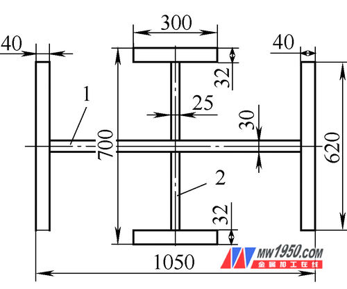
Figure 1: Structure of the "Ten" shaped steel member – 1. H-beam, 2. T-beam
3. Scope of Application
This method is suitable for welding low carbon steel, high-strength steel, and cast steel, and is particularly useful in the fabrication of "ten" shaped steel members within steel structures. It covers all stages from process selection and layout to cutting, H-beam and T-beam production, correction, edge machining, assembly, welding, top and bottom plate welding, straightening, marking, blasting, inspection, and final delivery.
4. Process Principle
The method utilizes an automatic H-beam production line. First, the web of the H-beam is cut intermittently, then the reserved part is transformed into a T-beam. After CNC cutting, the plates are assembled on an H-beam automatic machine, followed by CO2 base welding and submerged arc welding in an automatic ship position. Once the welding is inspected and approved, the H-beam is corrected using a flange corrector. The "ten" shaped components are then assembled on a tire frame, and the central welds are completed using CO2 primer, submerged arc welding, and cover welding.
5. Construction Process
(1) The process flow includes refining the process, layout, cutting, H-beam and T-beam production, assembly of the "ten" shaped components, welding of the web, non-destructive testing (NDT), correction, welding of accessories, cleaning, painting, inspection, and storage and delivery.
The "ten" shaped column at Jifeng Power Plant is 60.42 meters long, making it challenging to manufacture and transport. Therefore, it was divided into two parts by the design and owner’s team, and delivered to the site for on-site assembly. The factory production process is shown in Figure 2.
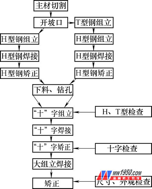
Figure 2: Production process of the "ten" shaped steel component
(2) Welding methods and material selection: The steel components were fabricated in two parts in the factory and then assembled on-site. To improve productivity and reduce deformation, small groove and low-energy welding techniques were used. For positioning and bottom welding, CO2 gas shielded welding was applied, while submerged arc welding was used for the cover weld. The selected materials included ER50-6 (φ1.2mm) for CO2 welding and H08MnA (φ4.0mm) with HJ431 flux for submerged arc welding.
6. Operational Procedure
The assembly of the "ten" shaped members involves three steps: producing the H-beam, producing the T-beam, and assembling the "ten" shaped member.
1. Cutting and unloading of parts: Parts are cut using a CNC flame cutting machine. The flanges and webs of the "ten" shaped members are cut horizontally on both sides using a CNC straight strip cutting machine, while irregular parts are cut using CNC profiling and semi-automatic machines. A trial piece is tracked for accuracy.
2. When cutting, add a 30mm welding shrinkage allowance to the length of the flange and web, but no allowance is needed in the width direction. If the length of the flange or web needs to be extended, the minimum length should be over 600mm, and the number of joints per part should not exceed two. Ensure that the arrangement of the flange and web is correct during nesting, with a seam distance of more than 200mm.
3. After cutting, mark the good parts with color codes, including the engineering name, steel grade, and part number. The groove shape is shown in Figure 4.
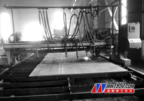
Figure 3: Real scene of CNC flame straight strip cutting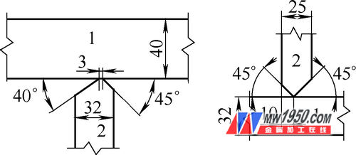
Figure 4: Groove form and size of H-beam and T-beam – 1. Flange plate, 2. Web
2. H-beam production: The H-beam can be assembled using an H-beam assembly machine. CO2 gas shielded welding is used for positioning, with a weld length of 40–50 mm, leg size ≤ 5 mm, and spacing of 300–400 mm. The dimensions of the H-beam must meet design requirements, with errors complying with GB50205-2001 standards. The vertical process of the H-beam automatic assembly unit is shown in Figure 5. Submerged arc welding is performed using a gantry-type special machine, with flux baked according to the process. Arc plates are placed at both ends of the member. The welding scene is shown in Figure 6. Correction of the H-beam is mainly done using a flange corrector if the flange thickness is less than 60 mm. For thicker flanges, a reasonable welding sequence is used along with manual flame correction.

Figure 5: H-beam and double T-beam assembly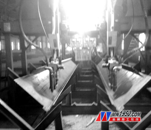
Figure 6: Submerged arc welding scene of H-beam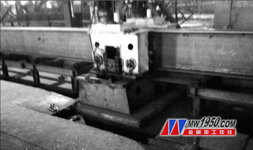
Figure 7: H-beam flange correction
3. T-beam production: The web of the T-beam is cut in a group, with intermittent cuts made at the center. After the H-beam is welded and corrected, the reserved portion is split into two T-beams. The double T-beam production is shown in Figure 8.
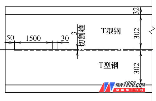
Figure 8: Production of double T-beam
4. Equipment selection for forming the "ten" shaped member: The "ten" shaped member can be assembled manually on a tire frame, as shown in Figure 9. The positioning is done using CO2 gas shielded welding, with the height of the positioning leg not exceeding 2/3 of the designed weld bead. The length of the positioning weld is 40–60 mm, and the pitch is 400 mm. The formation of the "ten" shape involves determining the assembly reference line, establishing it on the end web, and using it to support the strip. After preliminary positioning, the components are assembled with the reference line and process support bar as guides. The "ten" shaped member with the support rib plate is shown in Figure 10. The assembly of the "T" shaped members must be completed on the tire frame, with jacks pressed tightly between the components. The spot weld length between components is 40–60 mm, with a weld angle of 6 mm and a spacing of 300–400 mm.

Figure 9: Assembly of the "ten" shaped member – 1. Installation platform, 2. Tooling support, 3. Hydraulic cylinder, 4. "Ten" column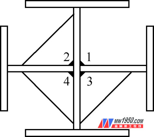
Figure 10: Schematic diagram of the ten-shaped member ribs – Note: 1 to 4 are welding sequences
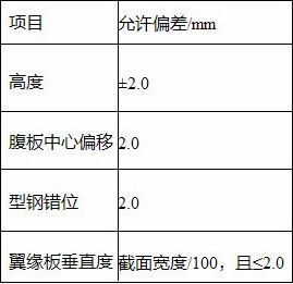
The allowable deviation of the "ten" shaped assembly is shown in Table 1.
Table 1: Allowable deviation of the "ten" column
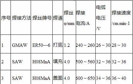
5. Welding of the "ten" shaped member: The welding is carried out using CO2 gas shielded welding, submerged arc welding, and capping. The welding parameters are shown in Table 2. To effectively control deformation, the welding is generally performed in the sequence shown in Figure 12, with continuous monitoring and adjustments made as needed. After welding, the process ribs are removed, and the components are cleaned and polished.
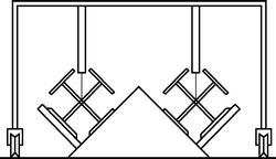
Figure 11: Welding of the ten-shaped member
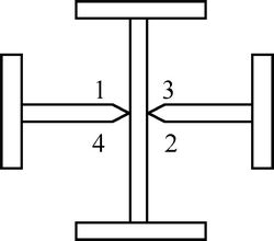
Figure 12: Welding sequence of “Ten†type components – Note: 1~4 is the welding sequence
Table 2: CO2 gas shielded and submerged arc welding parameters
6. Correction of the "ten" shaped member: The correction of the "ten" column is done using jacks and flame correction, without hammering or forced correction. One end is fixed, and the other is corrected using a jack. The correction method is shown in Figure 13. During heating, attention is paid to the orientation of deformation, and the temperature is controlled between 600°C and 800°C.
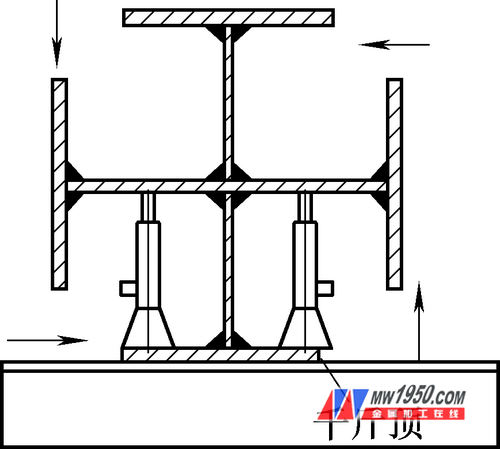
Figure 13: Correction of the "ten" shaped steel column
After correction, the upper end of the "T" shaped member is cut to control the length of the component.
7. Assembly preparation for Annex 1 on the "ten" component: Before assembling the parts, ensure they have been inspected and cleaned, with no burrs or gaps. Confirm the part numbers, directions, and dimensions before assembly. Check the number and specifications of the assembled "ten" component body, and ensure that local repairs and deformations have been adjusted. The "ten" shaped components are large, so the steel component body is placed on the assembly platform, and the horizontal reference is determined. The body is marked on the drawing according to the position and size of each component. The position includes the centerline, reference line, etc., and the position lines of each component should be clearly marked to avoid dimensional deviations caused by blurred lines. Assemble and weld the components in their structural positions to ensure optimal welding conditions and effective quality control. On the assembly platform, the components are assembled onto the body.
8. Assembly method of the steel component bottom plate: First, establish the horizontal platform of the assembly and adjust its level. Then draw the "ten" centerline and cross-sectional shape of the member on the bottom of the column. On the horizontal tire frame, the column bottom plate and the steel component body are assembled on the line, ensuring that the column bottom plate is perpendicular to the body and confirmed by a wire drop. After the assembly of the fourth "ten" component is completed, the center line of the steel column is marked with red paint on the column bottom plate as required, and the direction of assembly is accurately checked.
7. Materials and Equipment
(1) Material Requirements: Steel materials, welding materials, and coating materials used in steel structures must have quality certificates and meet design requirements and current national standards.
In addition to the quality certificate from the production plant, raw materials entering the factory must be witnessed, sampled, tested, and inspected on-site under the supervision of the contract and relevant standards. Inspection records should be made and test reports provided to Party A and the supervisor.
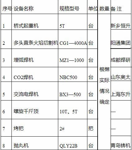
(2) Equipment Required for Fabricating the "Ten" Shaped Steel Components: The main equipment used is listed in Table 3.
Table 3: Main equipment usage
8. Quality Assurance Control
(1) Technical Specifications for Welding in Standard Building Steel Structures: JGJ81-2002, J218-2002; Acceptance Specification for Construction Quality of Steel Structure Engineering: GB50205-2001; Quality Inspection and Evaluation Standard for Steel Structure Engineering: GB50221-1995; Carbon Steel Welding Wire and Flux for Submerged Arc Welding: GB/T5293-1999; Ultrasonic Flaw Detection Method for Steel Welds and Classification of Flaw Detection Results: GB11345-1989.
(2) Quality Assurance Measures: 1. Strictly implement the company's quality assurance manual and procedure documents to prevent violations in the construction process. 2. Clarify the quality responsibilities of each process and check and implement them at all levels. 3. Welders and quality inspectors must be certified to work. 4. Conduct welding process evaluation and determine process parameters. 5. Perform spot weld tests for welders. 6. Maintain strict welding quality, keep a welding construction diary, and organize welder files.
9. Labor Organization and Safety Protection
(1) Labor organization includes 1 person, 2 welders, 4 riveters, 1 lifting crane, 1 inspector, 1 milling machine, and 1 safety officer.
(2) Safety protection: On-site construction personnel must strictly follow the current national "Construction and Installation Engineering Technical Regulations" and on-site safety technical measures and regulations. Additional emphasis is placed on the following points: 1. Special types of workers such as welders and cranes must receive training and pass exams to obtain certification. 2. Each beam (column) weighs about 5 tons. Always check the safety and reliability of the wire rope when lifting and transporting. 3. Operators should prevent burns. 4. Provide a comprehensive and skilled electrician for on-site service.
10. Project Examples and Benefit Analysis
In the national 11th Five-Year "863" plan key research project "600MW Coal-Fired Power Station Semi-Dry Desulfurization and Dust Removal Integrated Technology and Equipment," relying on the Huaneng Qifeng Power Plant 2 × 660MW dry desulfurization and dust removal integrated renovation project, this method was successfully applied. The project used over 10,000 tons of steel and produced a total of 126 "ten" shaped steel members, each weighing about 55.1 tons, achieving excellent results.
This method effectively solves the technical challenges in the production of "ten" shaped components, providing a complete and mature construction process. It not only saves labor, improves production efficiency, shortens the construction period, but also achieves significant economic and social benefits.
Bearing lubrication grease ,Industrial lubricant,Synthetic bearing grease ,High-load resistance, Adhesive lubricating oil
Yuyao Shuguang stainless steel bearing Co., LTD , https://www.shuguangbearing.com