Abstract: The metal thermoforming method can effectively improve the comprehensive mechanical properties of the product. The finite element simulation can provide a theoretical basis for controlling forging and product quality. Based on Deform3D's thermo-coupling rigid-viscoplastic finite element simulation technology, the secondary development of microstructure evolution is carried out, which can expand the finite element software's tissue simulation ability, and use this method to carry out the 20CrMnTi steel upset hot forming process. Computer simulations show the distribution of thermal parameters and the variation of internal grain size. The upset forming simulation of the rocker shaft proves that the tissue simulation can provide a theoretical basis for process improvement.
Key words: rigid viscoplasticity; finite element; grain size; microstructure evolution; hot upset
0 Preface
During high temperature forming, the metal will undergo dynamic and static recrystallization to produce new grains. The evolution of this microstructure determines the macroscopic mechanical properties of the product to a large extent [1, 2]. The use of thermal processing to control grain size and refine microstructure is an important means to improve the mechanical properties of products. Therefore, the macroscopic mechanical behavior and microstructure changes of the materials during the thermoforming process are studied, revealing their relationship with each other, and based on optimizing the process parameters, designing the plastic forming process and the post-forging cooling scheme, which solves the current process problems, It is very meaningful to improve product quality, and it is also a frontier topic in the comprehensive simulation of deformation process [3].
The finite element numerical simulation technology was developed with the improvement of physical simulation equipment and the development of computer technology. In view of the fact that the finite element method is currently the only analytical method that can give a comprehensive and accurate numerical solution to the plastic processing process, the numerical simulation of the material properties of the material is used in this paper.
Numerical simulation software is a basic tool for solving plastic machining problems. There are many mature commercial software for metal plastic processing on the market today. Such as DEFORM, MSC.MARC, MSC.SUPERFORM, Dynaform, etc., but these software only perform macroscopic deformation and temperature analysis calculation, do not consider macroscopic and microscopic coupling, do not have the simulation and prediction functions of microstructure evolution, or are simple The predictive power of the model is not necessarily suitable for the problem being examined. In this paper, through the secondary development of Deform3D, the tissue model suitable for the material is combined with the thermodynamic coupling calculation of the forming to simulate the tissue evolution during the thermoforming process.
1 Model establishment
In addition to changes in stress and strain in the thermoplastic deformation, complex microstructure changes occur, namely dynamic recrystallization, static recrystallization, grain growth, and the like. Studies have shown that the recrystallized grain size and percentage of recrystallized grains, in addition to the original grain size and trace element content, depend mainly on the temperature, strain and strain rate of the deformation and cooling process.
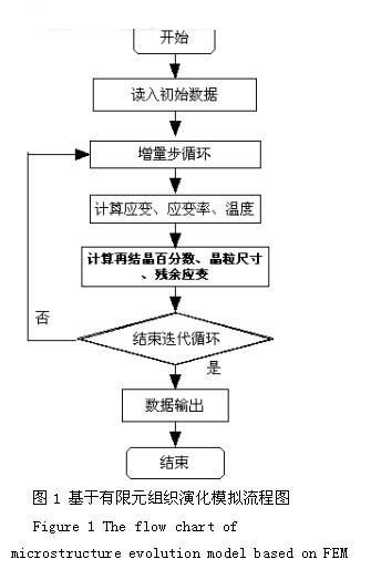
Due to the complexity of the thermoforming process, it is difficult to conduct on-site testing, and in the laboratory, only quantitative relationships between microstructure and macroscopic thermal parameters can be obtained under simple conditions. Through finite element simulation, the field information can be obtained very conveniently and economically, so the finite element can be used for the prediction and control of organizational evolution. Figure 1 shows the calculation flow of microstructure evolution during thermal deformation of materials using finite element simulation.
Through the thermal simulation test in the laboratory, a quasi-empirical mathematical model of the material can be obtained. Most of the empirical models are obtained by the experimental data regression to obtain the mathematical model of the Avrami form. In the process of finite element software development, the organizational model is discretized and calculated in each iteration step. The calculation process is shown in Figure 2.

The recrystallization model is coupled with the rigid viscoplastic finite element program. In the subroutine calculation, the dynamic recrystallization in the deformation process is first analyzed. In the actual calculation, the volume percentage of recrystallization is first judged. When X<0.95, judge, etc. Whether the effect change ε ​​is greater than the critical strain εc. If the equivalent strain is greater than the critical strain, the dynamic recrystallization process begins; when the dynamic recrystallization fraction X>0.95, it is directly converted to the relevant calculation of grain growth. By coupling the static recrystallization model with the heat conduction finite element, static recrystallization after unloading can be analyzed.
Deform3D is a commercial software for volume forming finite element process simulation developed by SFTC. The code of the user-defined subroutine is stored in def_usr.f. The finite element main program can calculate the user's self by calling the subroutine in the file. Define the value of the variable. So the key issue is the writing of this subroutine. The USRMSH subroutine contains all the variables in the finite element calculation. All of these variables can be modified by this user subroutine. The subroutine declares as follows:
SUBROUTINE USRMSH (RZ, DRZ, URZ, TEMP, DTMP, FRZA, FRZB, EFSTS, EFEPS, TEPS, RDTY, STS, EPS, DCRP, TSRS, DAMG, USRVE, USRVN, ATOM, HEATND, EPRE, VOLT, WEAR, DUM1 ,PRZA,DUM2,DUM3,HDNS,VF,DVF,VFN,TICF,GRNSZ,CURTIM,DTMAXC,BCD,NBCDT,NOD,MATR,NBDRY,KOBJ,NUMEL,NUMNP,NDSTART,NDEND,NUMFAC,NUSRVE,NUSRND,NPHASE , ISTATUS, NROUTINE, NONP)
Where TEMP is temperature, DTMP is the temperature increment of the iterative step, EFEPS (NUMEL) is the equivalent strain rate, and TEPS (NUMEL) is the plastic strain increment. In the subroutine, the above four basic parameters required for the organization simulation need to be read. For tissue simulation, the following parameters can be modified by USRMSH:
VF(NPHASE,*): Recrystallization score
DFV (NPHASE, *): recrystallization fraction increment
DFN (NPHASE, *): static recrystallization score
GRNSZ(*): grain size
2 Case analysis
The sector gear rocker arm shaft is widely used in engines, steering systems, and recirculating ball direction systems of various automobiles and the like. Due to the complicated working force and the harsh working environment, the rocker shaft has high mechanical properties. Therefore, it is important to simulate the process of tissue evolution during the thermoforming process, and to guide the process [4, 5].
The rocker shaft is formed in one step, the material is 20CrMnTi, and the mold material is 5CrNiMo. Because the workpiece is plane symmetrical, half of it is simulated, and the blank is divided into 52111 hexahedral units, a total of 7085 nodes, 1918 units of the upper mold, and 5823 units of the lower mold.
The material of the blank is 20CrMnTi, and its tissue model is as follows:
(1) Dynamic recrystallization model
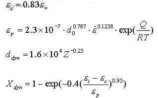
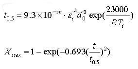
(2) Static recrystallization model
The organizational mathematical model was discretized and the simulation results were obtained by modifying the USRMSH subroutine.
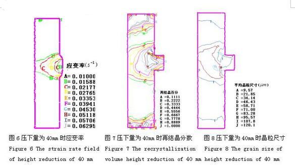
Figure 3 is a model diagram used for simulation. The main characteristic parameters reflecting the hot forming process of the material are temperature field (Fig. 4), strain and strain rate distribution (Fig. 5 and Fig. 6).
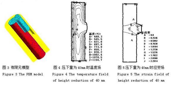
The change in the internal microstructure of the material during thermoforming can be explained by the degree of recrystallization and the size of the grain size (Figs. 7 and 8). The temperature field in the blank in the figure and the contour distribution of the strain and strain rate in the figure are in accordance with the variation of the thermal factors in the plastic processing. It can be seen from Fig. 7 that under this equivalent strain distribution condition, different degrees of recrystallization occur in various regions in the billet.
3 Conclusion
The thermal-coupling rigid-bonded finite element microstructure simulation technique was used to simulate the upsetting of 20CrMnTi structural steel rocker shaft. The obtained field information accorded with the deformation law. The numerical simulation results show that the finite element organization simulation can provide theoretical basis for the implementation of the rocker shaft thermoforming process and the control of product quality and production of qualified products.
references
[1] Kai Karhausen K. and Reiner Kopp R.. Model for Integrated Process and Microstructure Simulation in Hot Forming. Steel Research, 63 (1992) No.6 p.247-256
[2] Yong-Soon Jang, Dae-Cheol Ko, Byung-Min Kim. Application of the Finite Element Method to Predict Microstructure Evolution in the Hot Forging of Steel. Jounal of Materials Processing Technology, 101 (2000) 85-94
[3] Yang Hui, Zhang Zhiliang. Microstructure simulation study of warm precision forming. Heat treatment vol18, No.4, 2003, p1-p4
[4] Chen Huiqin, Liu Jiansheng, Guo Huiguang. Simulation study on grain shape change of Mn18Cr18N steel during hot forming. Journal of Metals, vol35, NO.1, 1999, p53-p57
[5] Qu Zhoude, Zhang Shihong, Xu Wei, Wang Zhongtang. Thermal coupling analysis of the fan-shaped rocker shaft extrusion. Thermal processing. 2004. 4
[6] Zhou-de Qu, Sh.H ZHANG. FEM analysis of forming and Microstructure and Prediciton of Properties for Wayshaft. Materials processing and design: modeling, simulation and application, NUMIFORM 2004, edited by S.Ghosh, JCCastro, and JK Lee, P1737-1741
Qu Zhoude 1,2 Zhang Weihong 1 Zhang Shihong 1 Wang Zhongtang 1
1 Institute of Metal Research, Chinese Academy of Sciences, No. 72, Wenhua Road, Shenyang, China
2 Taiyuan University of Science and Technology, No. 138, Hualiu Road, Taiyuan City
Lvl Beam for Australia Market
1) stronger, straighter, and more uniform.
2) much less likely than conventional lumber to warp, twist, bow, or shrink due to its composite nature.
3) Made in a factory under controlled specifications and reduce onsite labor.
LVL BEAMS:
Product Name: LVL Beam
Dimensions: 47*95*6000MM
65*95*6000MM
75*150*6000MM
100*150*6000MM
Allowable tolerance 0~1mm.
Material: radiate pine
glue;BOND A
Characteristic: finger joint
Price terms: FOB, CIF. CNF
Produce ability: 6000 cbm/month
Environment friendly.
introduction:
1)Quantity:around 40CBM/40HQ
2)Minimum Order:one 40HQ
3)Packging:For transportation of Ocean and Land, Inside Pallet is wrapped with 0.2MM plastic bag, Steel strip for strength,pallet packing
4)Payment:
a)30% in advance,70% against copy of B/L within 7 days
b)Irrevocable L/C at sight
5)Delivery time:within 15 days after receipt of the T/T deposit or original L/C
If you are interested in our products, please do not hesitate to contact kobe and for more information.
Best Regards


For more information and prices about the poplar Pine Lvl with yellow painting , please contact us , and we will give you our best price and services .

LVL Beam
Lvl Beam,Lvl Pine Beam,Lvl Engineered Wood,Pine Lvl
Fushi Wood Group , http://www.fushiplywood.com