Key words: CNC cutting machine, automatic nesting, intelligent, edging, intelligent continuous cutting, parameterized, drawing, sheet metal, unfolding
At present, the CNC cutting machine is the main machine for the production and processing of sheet metal parts. The cutting methods mainly include flame, plasma, laser and water jet. In today's economic globalization, CNC cutting machines are widely used in the machinery industry. In CNC automatic machining, CNC cutting machines and CNC programs have become the main factors affecting efficient cutting. In CNC cutting machines, mechanical precision, processing efficiency and reliability are guaranteed. Under the premise, the NC program is particularly important. The material saving, time saving, cost saving, and labor saving are mainly realized by the NC program. The NC program is automatically generated by the nesting programming software. Therefore, the advanced and reasonable application of the nesting software is The essential.
InteGNPS is a domestically produced, self-developed advanced CNC nesting programming software. It has a history of nearly 20 years. From the earliest DOS version to the current support for various versions of Windows, InteGNPS is made simple through continuous and uninterrupted version upgrades. The intelligent, stable and efficient featured software has absorbed the advantages of domestic and outerwear software on the basis of independent research and development, and developed intelligent CNC nesting programming software that is more suitable for national conditions.
InteGNPS software considers versatility, scalability, compatibility, modularity, etc. in the framework design, mainly in:
Versatility: Suitable for all kinds of CNC cutting machines, such as flame, plasma, laser, water jet, drilling, plane welding, etc.
Scalability: It is applicable to all kinds of CNC systems, and can support the code of all CNC cutting systems at home and abroad. Currently, it supports hundreds of codes and can be expanded at will;
Compatibility: Standard DXF is used as the exchange file, which is compatible with various drawing software, such as various versions of AutoCAD, electronic board CAXA, UG, ProE, SolidWorks, Catia, etc.
Modular: InteGNPS has six modules, 1 independent copyright CAD drawing module 2 manual / automatic nesting module 3 automatic programming module 4 quotation system 5 intelligent code conversion 6 intelligent graphics library & sheet metal expansion;
InteGNPS software uses a simple, clear structure and the use of steps: drawing parts drawing --> nesting --> programming --> CNC code simulation --> output NC simple workflow and usage habits, each of which can be separate Use separately.
The function of InteGNPS is very comprehensive. Here are some features that are combined with efficient cutting:
1. Intelligent continuous cutting and bridging technology
For some graphics that are not suitable for co-edge, bridging and intelligent continuous cutting technology play a big role, greatly reducing the number of firing perforations, not only speeding up the cutting speed, saving time, but also reducing the loss of the cutting nozzle and saving costs. . For example, bridging parts with less demanding process, as shown in Figure 1, can reduce the number of spark holes. Achieve a punch, cut the purpose of multiple parts.
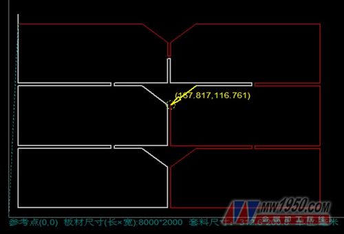
figure 1
2, manual and automatic co-edge
InteGNPS supports four co-edge methods with good processability and reduces scrap caused by thermal deformation.
Method 1: Use unclosed graphics (multi-line can be used), so that one punching continuously finishes a continuous line that is not closed, and achieves one punching and cutting multiple parts. This method needs to be connected by drawing to achieve continuous cutting. Certain skills, pre-consideration of compensation, good craftsmanship, can meet any co-edge requirements.
Method 2: Using the method of not closing the graphic + closing the graphic, such as cutting a cross first, and then cutting a outer frame, so that four parts can be cut, the method is simple in drawing and good in craftsmanship.
Method 3: When placing materials, place two common sides that require the co-edge parts in parallel, the spacing is the slit width, then decompose the second cut part block, and then modify the line segment that needs the common side to the outer contour bridge line. (If it is the inner contour, change it to the inner contour bridge wiring), and then mark the point of entry. At this time, the common side of the second part will not be cut to achieve the co-edge effect. This method requires reasonable selection of the cutting direction and the punching position. Otherwise, it is easy to cause two parts to be one big and one small. The co-edge method has limitations, and it is often easy to cause a reasonable punching position to be selected and affect the cutting quality.
Method 4: The co-edge method is intelligent automatic co-edge. As shown in the figure: first draw the part drawing, save it as a DXF file, then add the parts to be cut in the automatic nesting, set the part spacing to be equal to the slit width, start the discharging, define the cutting point after the arrangement, or you can Side edge definition (cut point can be copied), save the file and start programming. After popping up the programming parameters, select “Enable intelligent automatic co-edge option†to set the part spacing and the spacing of the parts in the nesting drawing are basically equal, then Set the allowed pairing error (the part spacing in the nesting diagram may not be accurate enough) and finally confirm the programming. All co-edge pairing is done automatically by the programming software. This method is simple and fast. To obtain better craftability, it is necessary to define a reasonable point of entry and cutting direction.

Figure 2 Intelligent automatic co-edge, just hit a tick
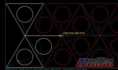
Figure 3 Co-edge cutting saves material and saves time
3. Parametric drawing part drawing, parameterized nesting, parameterized sheet metal unfolding
The intelligent library contains basic graphics, curves, CNC cutting, sheet metal unfolding, bending calculation, mathematical calculation, box expansion and other common basic graphics, which meet most of the user's needs. Parametric drawing and nesting are simple, convenient and practical. Efficient features improve work efficiency and reduce the cost of the enterprise. Another feature of the intelligent library is open source, which allows users to develop small program scripts in C language and expand the smart library. C language scripts can be run without compiling. For customers who are interested, capable, and knowledgeable in C programming, this feature can reduce a lot of repetitive and complicated drawing work for them, flexible and convenient, compared to other non-redevelopable graphics libraries or sheet metal development software. More advanced and flexible.
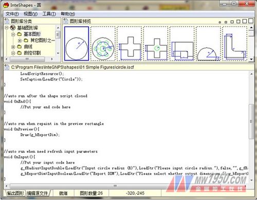
Figure 4 Intelligent graphics library open source code, can be redeveloped

Figure 5 Parametric rectangular cutting nesting
In summary, the nesting software plays a decisive role in CNC cutting. In order to achieve efficient cutting and cost reduction, it is not only the purchase of a machine with advanced functions and reliable quality, but also the application of nesting software and software in CNC. Cutting plays a decisive role, and companies should go beyond the misunderstanding of focusing on hardware rather than software.
Fridge Magnet,Flexible Magnet,Artpaper Fridge Magnet
Maghard Flexible Magnet Co., Ltd. , http://www.dg-magnet.com